
اتصل
هاتف
+0086-371-86162511
عنوان
تشنغتشو ، الصين
block diagram representation of sand mill process

Production process of manufactured sand Download
Ordinary Portland cement (OPC) is a conventional material used to construct rigid pavement that emits large amounts of carbon dioxide (CO2) during its manufacturing process, which is bad for theFrom a control-engineering viewpoint, this design strategy focuses on the control (indirectly) of the properties of the regenerative vibration process, by 'tuning' the machine dynamics at the...; Block diagram of the milling process. Download
احصل على السعر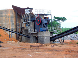
Rapid Manufacturing of Sand Molds by Direct Milling
A schematic diagram of the cutting of a sand block is shown in Fig. 8. The machining of a sand block with binder is a serious of interrupted cuts. The essence of Download scientific diagram Schematic representation of sand casting process. from publication: Phase Change Materials in Metal Casting Processes: A Critical Review and Future PossibilitiesSchematic representation of sand casting process.
احصل على السعر
Block Flow Diagram processdesign Northwestern
A block flow diagram (BFD) is a drawing of a chemical processes used to simplify and understand the basic structure of a system. A BFD is the simplest form of the flow diagrams used in industry. Schematic representation of the grinding process: a -ball and b -vibratory mills simplicity of design; relatively low energy consumption due to a small number of working nozzles; possibility of...4. Schematic representation of the grinding process: a
احصل على السعر
What is a Process Flow Diagram Lucidchart
A Process Flow Diagram (PFD) is a type of flowchart that illustrates the relationships between major components at an industrial plant. It's most often used in chemical The casting process parameters of the mill roller have been identified by using cause and effect diagram. The parameters such as permeability, pouring Design and analysis of sand casting process of mill roller
احصل على السعر
Sand Casting an overview ScienceDirect Topics
A schematic diagram for the sand casting process is shown in Fig. 6.5. A pattern is made in the shape of the desired part, but enlarged to account for shrinkage and machining A block diagram is a simplified visual representation of a complex system or process using interconnected blocks, arrows, and lines. It is mostly used in engineering, hardware, and software tools. Block diagrams simplify workflows, organize processes, or showcase relationships between different systems.Free Block Diagram Maker Create Block Diagram Canva
احصل على السعر
Sand Casting Process: Definition, Terminology,
The sand casting process is used for the creation of cylinder blocks, machine tool beds, pistons, etc. where you can produce the components in bulk which is not possible by means of the machining process. All the Simulink is a graphical modeling and simulation environment for static and dynamic systems. You can create block diagrams, where blocks represent parts of a system. You can connect blocks to other blocks to form What Is a Block Diagram? MATLAB & Simulink
احصل على السعر
Block Diagram Learn about Block Diagrams, See Examples
A block diagram is a specialized, high-level flowchart used in engineering. It is used to design new systems or to describe and improve existing ones. Its structure provides a high-level overview of major system components, key process participants, and important working relationships. Back to top.Figure 2 shows a schematic representation of a mill housing of a FM stand. The inner rolls in contact with the strip are called work rolls, and the outer and larger rolls are called backup rollsSchematic diagram of a hot strip mill stand ResearchGate
احصل على السعر
SandCasting%of%Metals% Materials Education (MatEdU)
6" " skim"off"the"top"layer"(slag)"of"the"liquid"metal"with"aslag"stick"and"apair"of"pliers."Steadily"pour" the"molten"metal"into"the"pouring"cup."This"will"aid"inBefore we learn the steps involved in the process, it is important to understand the parts or the elements used in the casting process. Refer to the sand casting diagram below as you learn about the elements. Fig 1: Sand Casting Diagram. Cope and Drag: The top and the bottom part of a casting arrangement are called cope and drag Sand Casting: Exploring Process, Steps, Defects, and More
احصل على السعر
Block Diagram of Control System Electronics Coach
Basically block diagram of a control system pictorially represents a system. By using visual illustration, even a very complex system can be simplified for the purpose of analysis. The block diagram representation of a system is nothing but an interconnection of multiple elements of the system. This interconnection using blocks allows aJust 3 minutes to learn to use Lucidchart. Create your first block diagram. You can start from a blank canvas, or you can get a head start by using a template or importing a document. Fill out your diagram with shapes and connecting lines, then write in text to describe what they represent. Format your diagram and adjust the styling to make itBlock Diagram Maker Free Block Diagram Online Lucidchart
احصل على السعر
What is a Process Flow Diagram Lucidchart
A Process Flow Diagram (PFD) is a type of flowchart that illustrates the relationships between major components at an industrial plant. It's most often used in chemical engineering and process engineering, though its concepts are sometimes applied to other processes as well. It’s used to document a process, improve a process or model a new Collaborative block diagram maker to easily visualize systems and processes, and document and analyze their functional blocks and relationship. Create a Block Diagram. Intuitive visual tools for complex system designing. Real-time collaboration to work together with stakeholders. Professional shapes and templates to get a head start.Block Diagram Maker Block Diagram Software Creately
احصل على السعر
Processes of Waste Water Treatment: 4 Process (With Diagram)
ADVERTISEMENTS: This article throws light upon the four processes of waste water treatment. The four processes are: (1) Preliminary Treatment (2) Primary Treatment (3) Secondary or Biological Treatment and (4) Tertiary or Advanced Treatment. 1. Preliminary Treatment: As already stated, preliminary treatment involves the removal of floating The block diagram for this decomposition is given in Figure 3.1. U(s) V(s) V(s)/U(s) Y(s)/V(s) Y(s) Figure 3.1: Block diagram representation for (3.17) Equation (3.17a) has the same structure as (3.6), after the Laplace transformation is applied, which directly produces the state space system equation identical to (3.9). It remains to find3.1 State Space Models Rutgers University
احصل على السعر
11.5: Block Diagrams and Transfer Functions of Feedback Systems
Block Diagrams: Fundamental Form. The topology of a feedback system can be represented graphically by considering each dynamical system element to reside within a box, having an input line and an output line. For example, a simple mass driven by a controlled force has transfer function P, which relates the input, force u(s), into the output2. INTRODUCTION • A Block Diagram is a shorthand pictorial representation of the cause-and-effect relationship of a system. • The interior of the rectangle representing the block usually contains a description of or the name of the element, gain, or the symbol for the mathematical operation to be performed on the input Block diagram representation PPT SlideShare
احصل على السعر
Control Systems Block Diagram Reduction Online Tutorials
Step 1 − Find the transfer function of block diagram by considering one input at a time and make the remaining inputs as zero. Step 2 − Repeat step 1 for remaining inputs. Step 3 − Get the overall transfer function by adding all those transfer functions. The block diagram reduction process takes more time for complicated systems.Simulink is a graphical modeling and simulation environment for static and dynamic systems. You can create block diagrams, where blocks represent parts of a system. You can connect blocks to other blocks to form systems and represent more complex functionality. The primary function of Simulink is to simulate behavior of system components over time.What Is a Block Diagram? MATLAB & Simulink MathWorks
احصل على السعر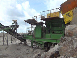
Dynamic modelling and simulation of a hot strip finishing mill
Block diagram representation of the basic mill unit. Thus, it has been shown that if the block diagrams of individual stands are linked together so as to create a block diagram of the entire finishing mill, there will be a seamless flow of disturbance variables between the stands, and no inter-stand disturbance signals will have to be Reliability Block Diagram (RBD) analysis is a methodology for assessing and calculating the reliability and availability metrics of complex systems using a graphical depiction of the system. RBD techniques are most often employed to model complex systems, especially those that incorporate redundant components and repair data. Within RBD, thereA Deep Dive into System Modeling using Reliability Block Diagram
احصل على السعر
Lecture # 4 Block Diagrams KorAcademy
neither representation is limited to a particular analysis and design technique, block diagrams are usually used for s-domain analysis and design, and signal-flow graphs for state-space analysis and design. Summing Junction When multiple subsystems are interconnected, a few more schematic elements must be added to the block diagram.
احصل على السعر- معامل مطاحن الدقيق
- كسارة الحجر المتنقلة المقاول 0 4 مم
- قائمة شركات تعدين النيكل في زامباليس
- crushed limestone for concrete
- وكم من صواني الرمال خام الكوارتز استخدام القيمة فقط
- وصف مفصل لوصف كسارة الفك
- تصدير المنتجات من الفلبين
- double head stem crusher
- طحن مطحنة للبيع خام طحن مطحنة سعر آلة طحن مطحنة
- الحجر معدات التعدين محطم
- معجون الألومنيوم عملية مطحنة الكرة
- How To Build Foot Power Grinding Wheel
- موتور فکی سنگ شکن
- كسارة الكوارتز الطرد المركزي
- تولید سنگ آهن در آفریقا